

Equipment & Software for Geophysical Surveys: Design, Manufacture, Support, Supply
Non-polarizable porous pots
The non-polarizable electrode is designed for grounding receiving lines during geophysical surveys using methods like Self Potential (SP), Induced Polarization (IP), and Magnetotelluric Sounding (MT). It’s also used for measuring stray currents and electrode potentials, working as a reference electrode.
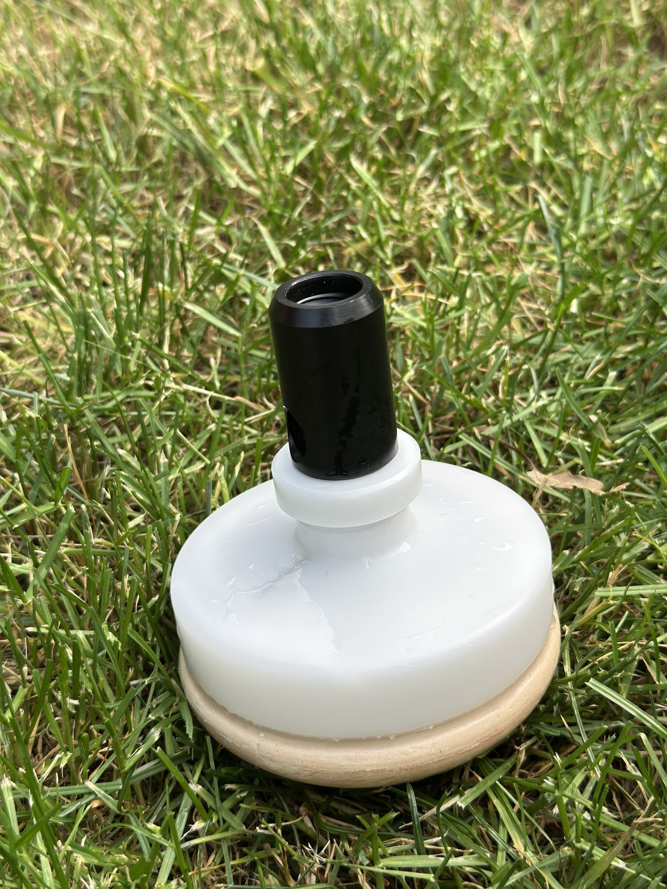
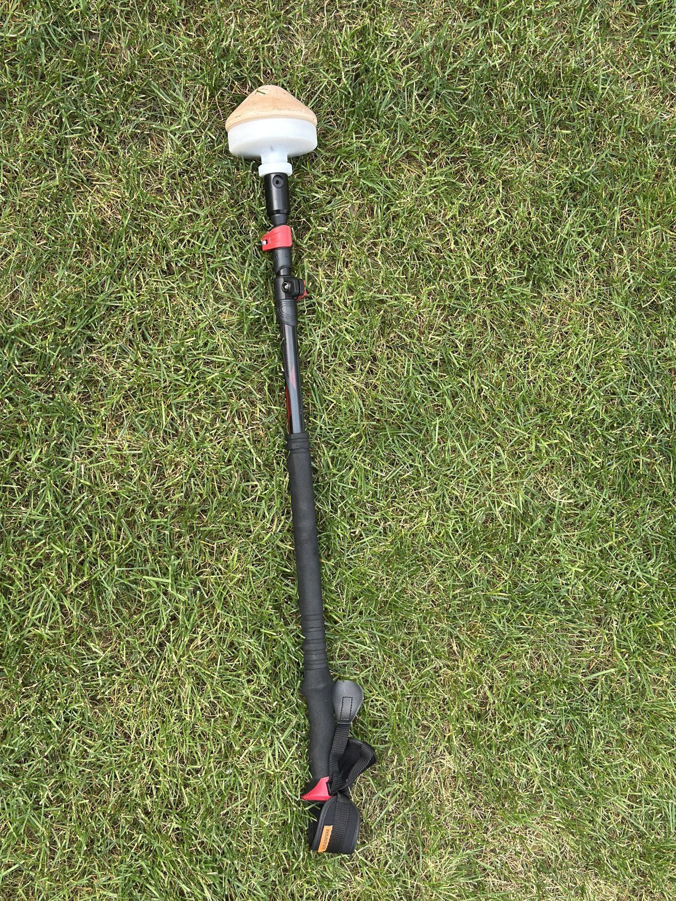
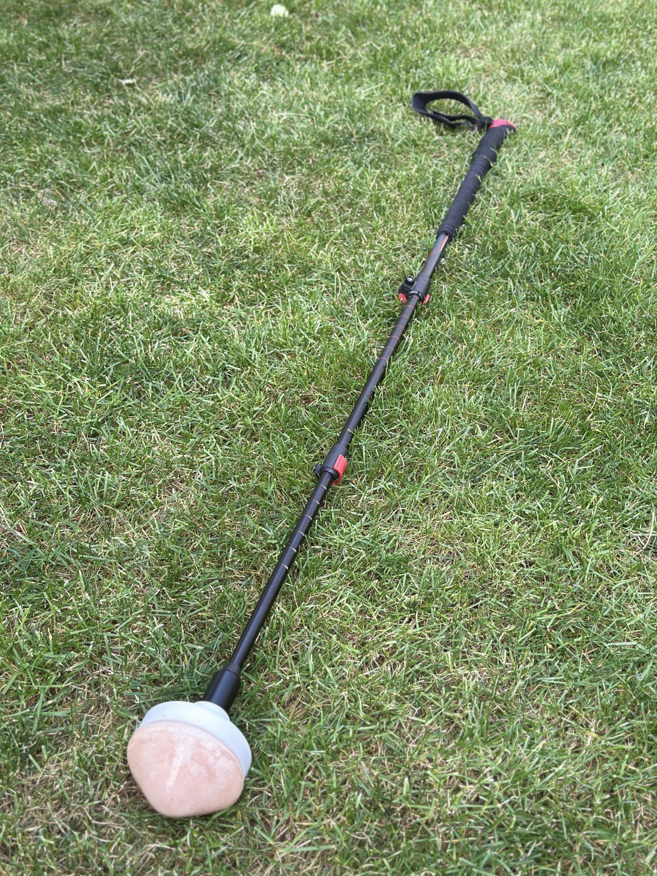
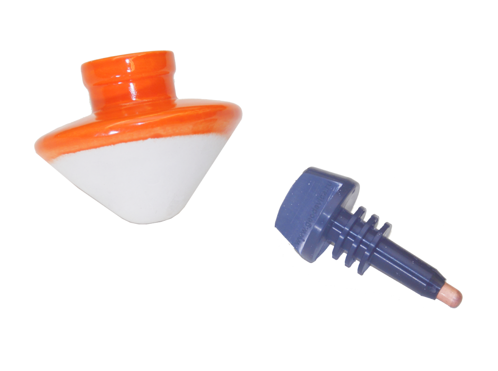
The new design allows to check the solution level without opening the plug. The plug now features a secure screw connection, which also makes it possible to attach a telescopic walking stick with—transforming the electrode to portable reference electrode or as aquatic non-polarizable electrode.
We also manufacture maintenance-free lead-chloride non-polarizable electrodes and winter models with a low-temperature electrolyte that ensures reliable operation down to –25 °C.
A bit of theory
What sets non-polarizable electrodes apart is their low and stable electrode potential. This stability comes from how the copper rod interacts with the ground—through an ionic medium that creates a balanced electrochemical system. The overall potential of the electrode includes:
- The metal’s electrode potential in the electrolyte (the potential difference where the electrolyte meets the ceramic)
- The diffusion potential (the potential difference where the ceramic meets the soil)
To keep these potentials low and steady, all electrodes in a system should be made the same and used under similar conditions—especially temperature. Stability depends both on the electrode potential and on the combined effect of membrane and diffusion potentials. That’s why it’s important to keep the copper rods clean and free from oxidation, and the ceramic parts intact and undamaged.
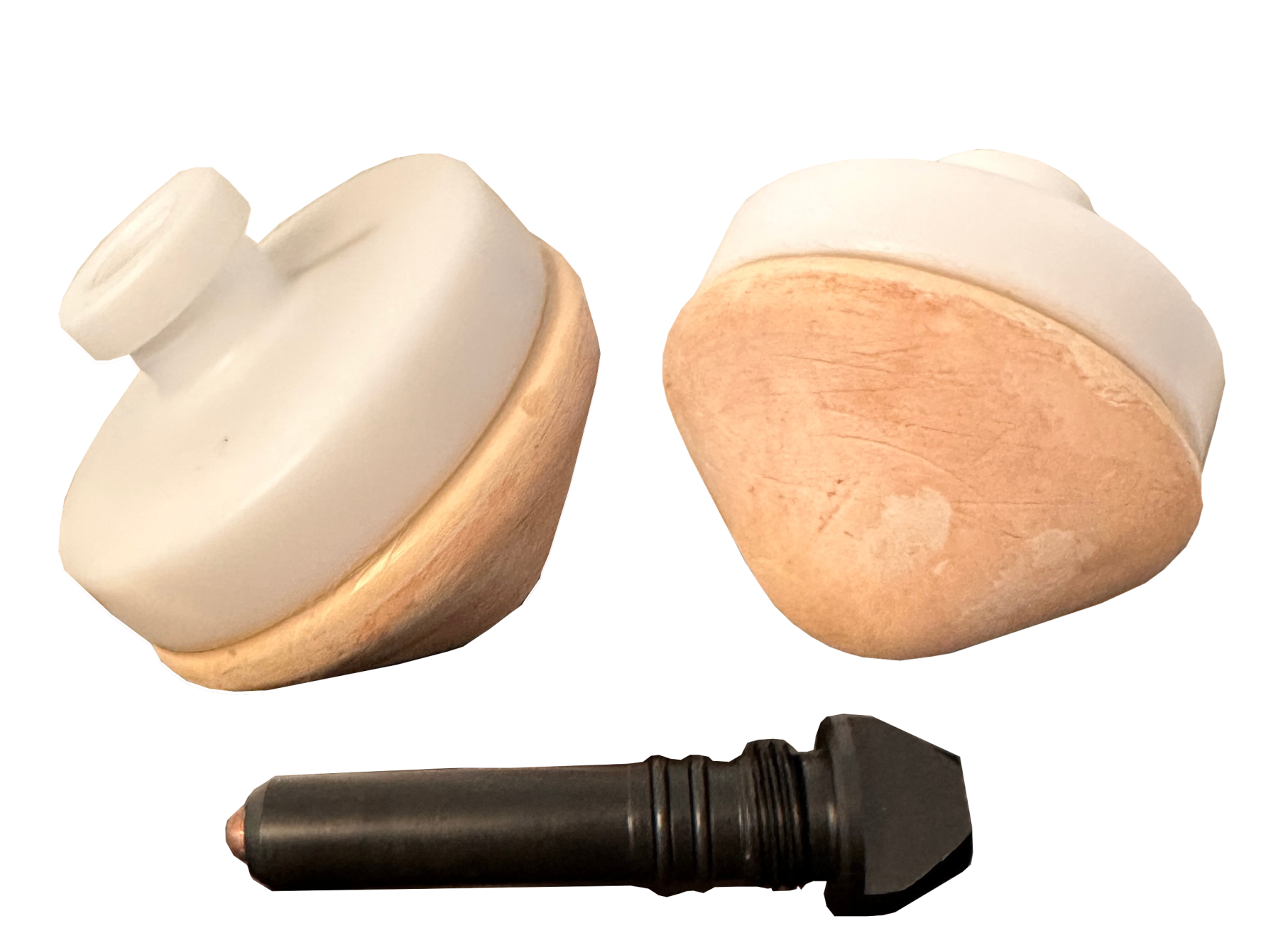
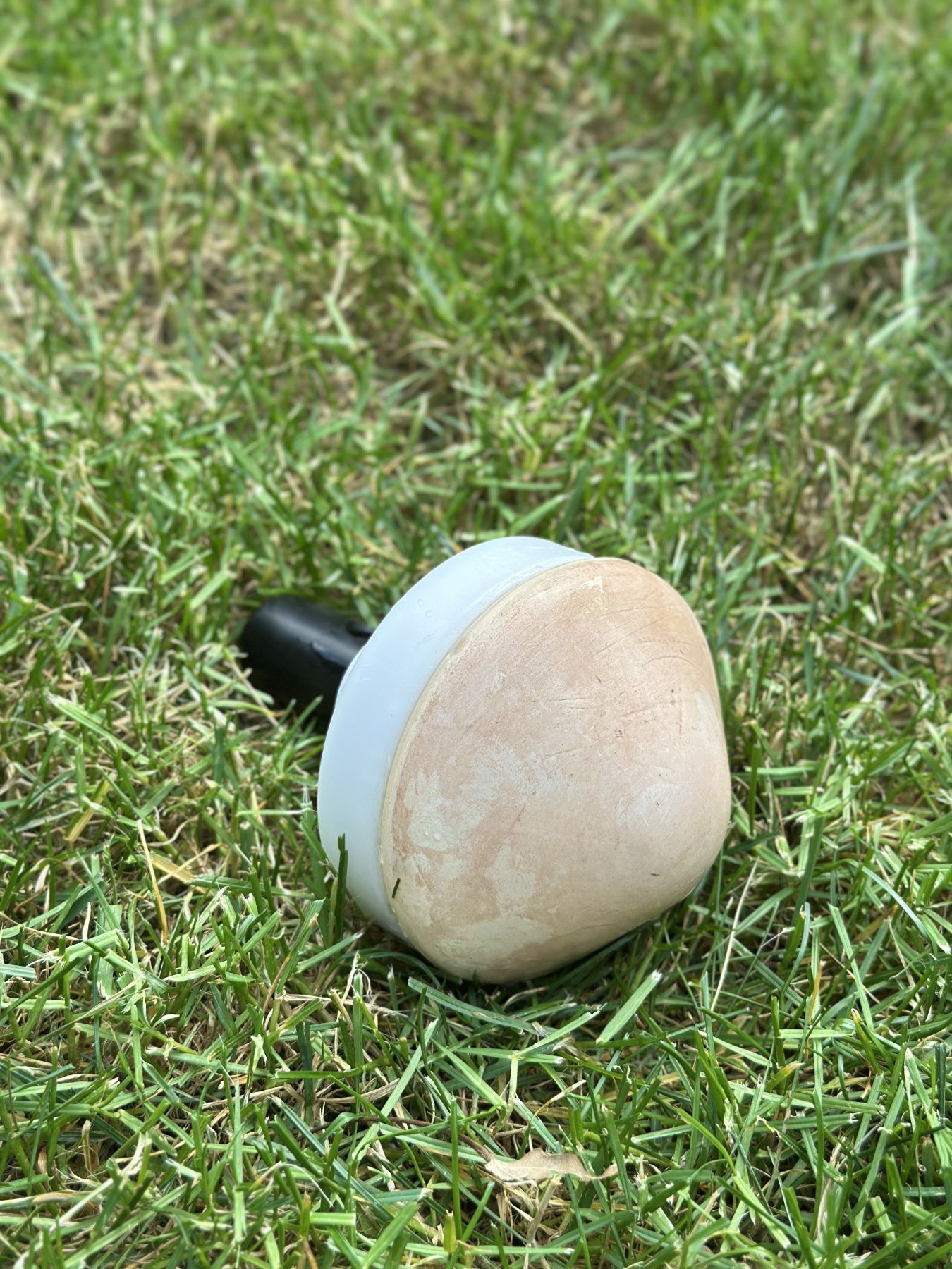
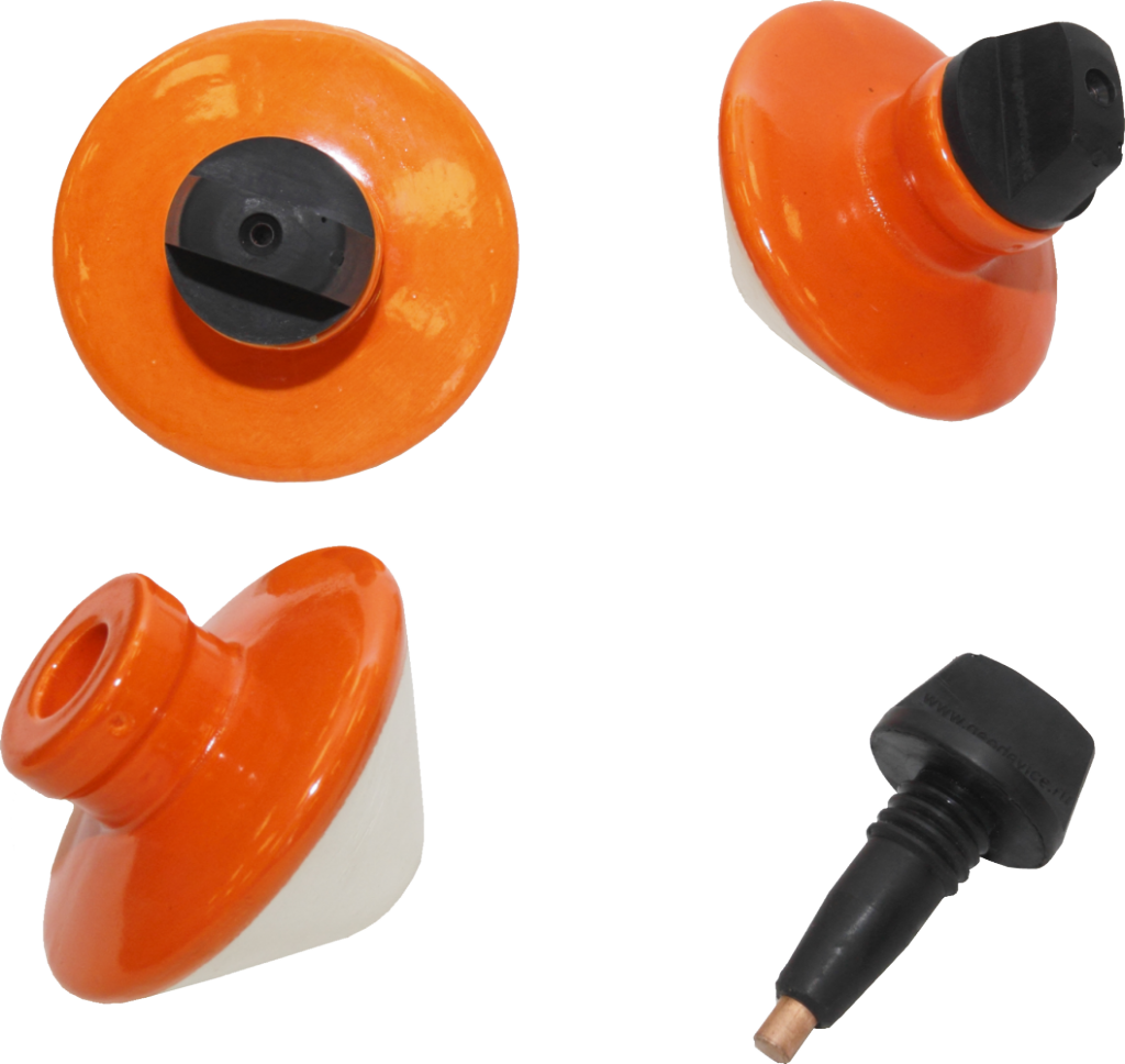
The top of the electrode housing has a glazed coating to avoid accidental electrical contact with the electrolyte and to slow down evaporation. At the top of the copper rod, there’s a socket for a single-pole plug. The part of the rod that sits in the electrolyte is hemispherical and polished, while the rest is embedded in a polyurethane plug to protect it from oxidation.
Operational Guidelines for Electrode Use and Maintenance
To prepare the electrolyte, use a saturated solution of copper sulfate (CuSO₄). If distilled water is not available, alternatives such as boiled snow, rainwater, or demineralized water may be used. All electrodes should be filled simultaneously using the same batch of prepared electrolyte. Additionally, a small quantity of clean, fine copper sulfate crystals should be added to each electrode. Once filled, the electrodes should be placed in moist soil or a container filled with wet sand and left to condition for a minimum of two hours.
To improve the consistency of the electrolyte, thickening agents may be added. Below is a list of recommended additives along with their suggested concentrations:
| Thickener | Concentration | Characteristics |
| Agar-agar | 0.5–1% | Viscous, forms a gel-like consistency, performs well in hot conditions |
| Starch | 10% | Requires heating the electrolyte to boiling point – chemically resistant cookware needed |
| Carboxymethyl cellulose (CMC) | 0.5–2% | Stable, inexpensive, easy to prepare |
| CMC + Glycerin mixture | CMC 0.5–1% + Glycerin 5–10% | Improves resistance to drying and temperature fluctuations |
Before beginning work, it is essential to measure the potential difference between the electrodes placed in close proximity to each other in moist soil. The potential difference between the working pair must remain stable over time and should not exceed ±2 mV. If the electrodes do not meet this requirement, the following corrective actions should be taken:
- Polish the working surface of the copper rods using canvas cloth.
- Replace the electrode porous part (pot), if necessary.
If polishing the hemispherical surfaces does not sufficiently reduce the potential difference between the copper rods, the working surfaces may be coated with a layer of electrolytic copper through electroplating. During operation, it is essential to regularly monitor the potential difference between the electrodes and take appropriate measures to ensure their reliable performance. The following guidelines should be followed:
- Ensure that the electrolyte level within the ceramic part consistently remains above the working surface of the copper rod.
- Maintain, as far as possible, equal temperature conditions for both electrodes. A temperature difference of just 1°C between electrodes can result in a potential difference of approximately 1 mV.
- Keep the upper part of the electrode, particularly the top of the lid, clean and completely dry at all times.
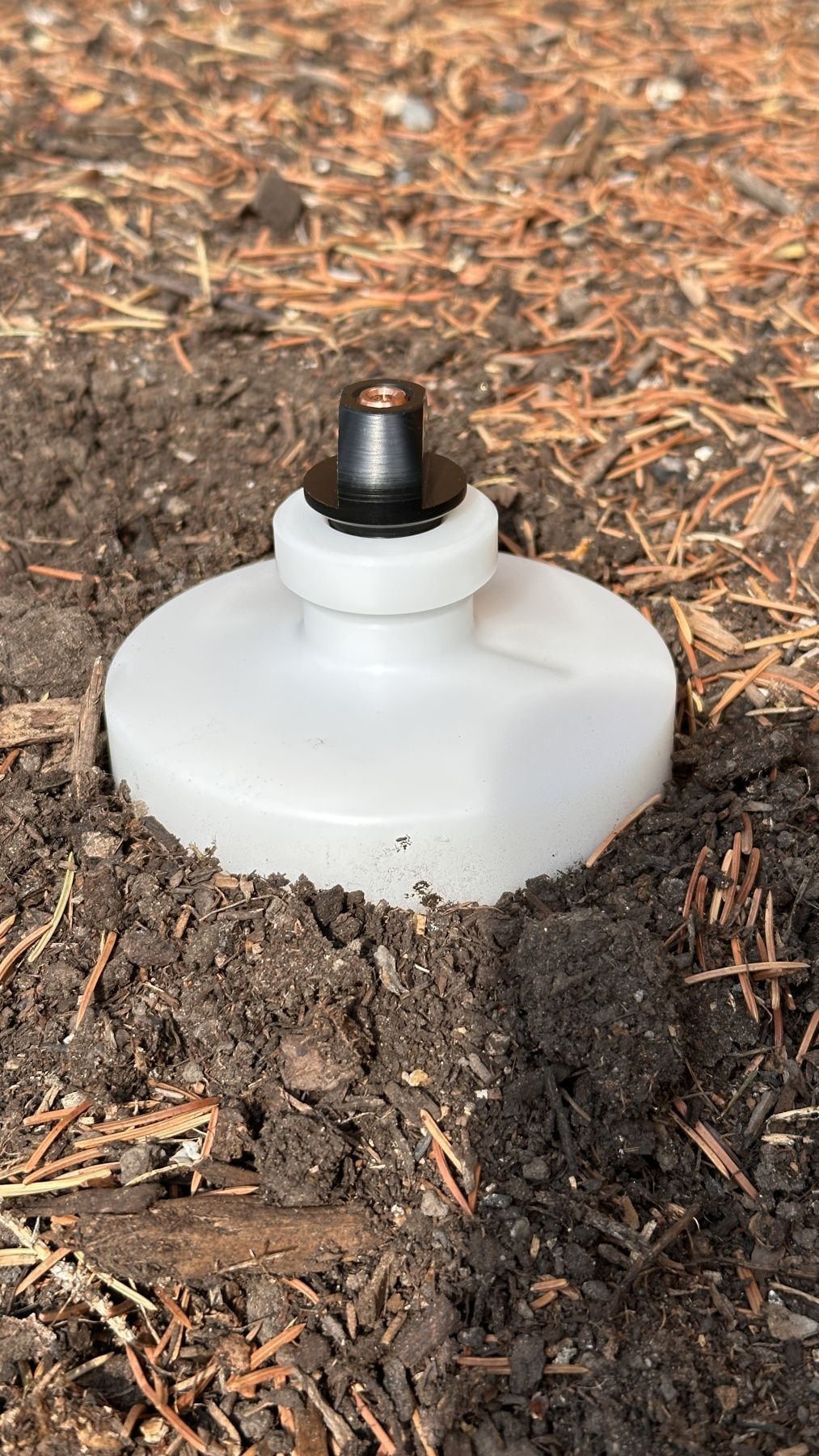
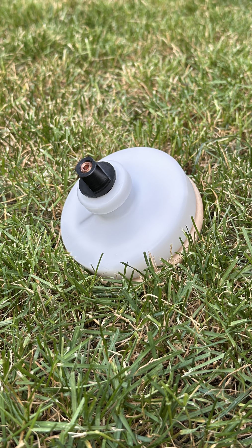
When in use, electrodes should be placed in holes filled with loosened soil to ensure full contact between the ceramics surface and the surrounding ground. During breaks in measurements, the electrodes should be positioned side by side and connected with a wire.
Important: Electrodes must never be stored with copper sulfate solution remaining inside the electrode. After completing work or before extended periods of non-use, the solution must be discarded, and both the lip and the pot should be thoroughly rinsed. The pot should then be soaked in potable water for 1–2 days, with periodic water changes, followed by drying.
This soaking and rinsing process is critical for removing residual copper sulfate. If left in the ceramic pores, copper sulfate can crystallize and degrade the material—initially increasing permeability and eventually causing physical damage. Crystallization can also compromise the seal between the copper rod and the rubber lid. Additionally, before long-term storage, it is recommended to lubricate the lid surface that contacts other surfaces with a silicone-based grease to prevent wear.
These electrodes are commonly used in mineral exploration, engineering geology, hydrogeology, archaeology, and various geotechnical applications.
Delivery set:- Electrode ceramics pot
- Plastic lid with embedded copper electrode
- Telescopic rod with plastic lip and embedded copper electrode
| Electrochemical composition | copper - solution of copper sulfate (CuSO4) |
| Plug material | copper, polyurethane |
| Body material | porous ceramics with glaze at upper part |
| Electrolyte | saturated solution of copper sulfate in distilled water |
| Maximum volume of solution | 70 ml |
| Limits of allowable difference in 2 copper rod electrodes self-potentials in electrolyte | ±1 mV |
| Limits of allowable difference in 2 copper rod electrodes self-potentials in potable water | ±2 mV |
| Resistance of 2 series-connected electrodes in potable water | <1 kOhm |
| Permeability of ceramics membrane | electrolyte volume decreases no more than by half in 8 hours in electrode |
| Diameter | 9.5 cm |
| Height | 11 cm |
| Mass of a dry pot | <0.4 kg |
| Working temperatures | 0 ÷ +50 °С |